/ We will do attentively..   Collection / Supposes / E-mail / Site map
Warm congratulation NINGBO CIE INDUSTRY AND TRADE CO.,LTD website clear~
 Product List

Auto Bearings


Front Wheel Hub Bearings
  Rear Wheel Hub Bearings
 

Tensioner&Idler Bearings


Clutch Release Bearings


Wheel Hub Bearing(One Generation)


Wheel Hub Bearing( second generation)


Wheel Hub Bearing ABS System


Water Pump Bearing


Automotive Tapered Roller Bearings


Steering Wheel Bearings


Universal Joint Kits

    Automobile Center Support Bearing
  Steering Gear Box Bearings
  Special Non Standard Auto Bearing
  Automobile Alternator Bearing
  Automotive Air Condition Bearings

Industry Bearing


Deep Groove Ball Bearings
  Angular Contact Ball Bearing
 

Cylindrical Roller Bearings


Self-Aligning Ball Bearing


Spherical Roller Bearings


Tapered Roller Bearings


Bearing Units


Thrust Bearings


Needle Roller Bearings


Linear Bearings


Special Non Standard bearings

Power Transmission Parts


Ball leading Screw


Linear Motion Shaft

  Linear Guide Rail and Block Assemblies
  Precise Crossing Guide Rail

Auto Steering Gears


Worm and level Steering Gears


Rack and Pinion Type Steering Gears


Recirculating Ball Type Steering Gears


  Power Transmission Technology

ACME Screw Data Ball Screw Data Ball Screw Selection Bearing Mounts Data Design And Engineering
Linear Guides Linear Guideway Info RFQ of Linear Guider Rail And Block    

Specification
Equipment: Transfer Table
Screw Orientation: Horizontal
Load Supported on Dove Tail Ways: .20 Coefficient of friction
Load is 2500 lbs. Max (combined weight of product and table)
Stroke Length: 38"
Travel Rate: 600 inches per minute (Max.)
Input RPM: 2400
Duty Cycle: 20 cycles per hour, 16 hours per day, 250 days per year
Required Life: 5 years
Step 1: Determine Required Life (Inches)
38"/stroke * 2 strokes/cycle * 20 cycles/hr * 16 hrs/day * 250 days/year * 5 years = 30,400,000 inches

Step 2: Determine Thrust Load on Ball Screw
Multiply the thrust load by the coefficient of sliding friction (for horizontal application):
2500 lbs. * .20 Coefficient of Friction = 500 lbs.
Use this load for life calculations

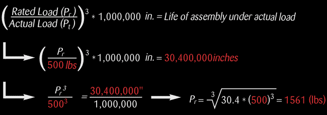
Step 3: Determine Required Ball Screw Dynamic Axial Loading to Achieve Required Life (page 7 of catalog):
Using formulas on page 7, input the 500 lbs. thrust load (Or equivalent load) and the required life. The result is the minimum rated load for a ball screw to achieve the required life.Rated Load Actual life of assembly under actual load

Step 4: Determine Lead of the Screw:
Travel Rate (pg 10 of catalog):

USE THIS QUICK REFERENCE CHART TO SELECT APPROPRIATE BALL SCREW


Model

Screw
Diameter
x Lead

Screw
Rated
Load

Screw
Minor
Diameter

Catalog
Page
Number

Model

Screw
Diameter
x Lead

Screw
Rated
Load

Screw
Minor
Diameter

Catalog
Page
Number

R10

.375 x .125

150

0.300

22

R45, R47

1.150 x .200

2,450

1.020

38

R11

.375 x .125

300

0.300

23

R46*

1.150 x .200

490

1.020

38

R15*

.375 x .125

25

0.300

22

R48

1.063 x .625

3,300

0.925

39

R16*

.375 x .125

50

0.300

23

R50

1.500 x .500

9,050

1.260

40

R20, R23

.500 x .500

850

0.400

24-25

R50A, R51A

1.500 x .500

12,900

1.260

41

R21*, R22*

.500 x .500

140

0.400

24-25

R53, R54

1.500 x .250

4,250

1.375

42

R30, R31

.631 x .200

825

0.500

26

R54A

1.500 x .250

6,400

1.375

43

R30A

.631 x .200

1,650

0.500

27

R55, R56

1.500 x 1.00

8,000

1.140

44

R32*

.631 x .200

170

0.500

26

R57

1.500 x .4375

10,500

1.140

45

R34

.750 x .200

1,900

0.650

28

R58

1.500 x 1.875

7,350

1.190

46

R35

.750 x .200

950

0.650

29

R60, R63

2.250 x .500

19,800

1.860

49

R36

.750 x .200

160

0.650

29

R60A

2.250 x .500

29,700

1.860

50

R37

.750 x .500

3,400

0.630

30

R61

2.000 x 1.00

22,500

1.730

47

R38*

.750 x .500

600

0.630

30

R62

2.000 x .500

18,000

1.730

48

R40, R41

1.000 x .250

1,625

0.840

31

R70

2.500 x .500

22,000

2.220

51

R40A

1.000 x .250

3,250

0.840

32

R71

2.500 x 1.00

26,500

2.220

52

R40RF, R41LF

1.000 x .250

3,250

0.840

34

R74

2.500 x .250

6,300

2.320

53

R40B

1.000 x .250

4,500

0.840

33

R75

2.500 x 1.50

32,500

2.100

54

R42

1.000 x .250

3,450

0.870

35

R80

3.000 x .660

42,000

2.480

55

R43

1.000 x .500

4,250

0.870

36

R90, R91

4.000 x 1.00

85,000

3.338

56

R44

1.000 x 1.00

2,300

0.870

37

* DENOTES STAINLESS STEEL MODELS


IdeaBall Screw Selection:
Load rating: Requires ball screw operating load capacity of 1,561 lbs. Minimum smallest diameter screw with 1,561 lbs. (min.) operating load and a .250" lead is the R40 (page 31 of catalog)
Ball Screw Selection

Step 5: Calculate Length Between Bearing Supports:
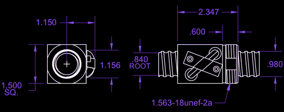
Length between bearings = Stroke length + Ballnut length + Desired over-travel
38" stroke + 2.347 nut length (page 31 of catalog) + 1" over-travel = 41.347" between bearings
(use this length for column load and critical speed calculations)
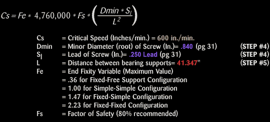
Step 6: Calculate End Fixity Based on Critical Speed Limits (page 7-8 of catalog):
Using formula for Critical Speed, rearrange to solve for Fe (End Fixity Variable)
End Fixity Based on Critical Speed Limits
Equations below will solve for the minimum end fixity factor based on Travel Rate (600 in/min.)
minimum end fixity factor
Thus a Fixed-Simple (Fe = 1.47) is the proper selection
Step 7: Actual Calculated Critical Speed:
This calculated critical speed is based on the Fixed-Simple end fixity arrangement. It is the maximum safe linear speed with this mounting arrangement, screw model and between bearing supports distance. If greater speed is required, a Fixed-Fixed arrangement can be used, recalculate maximum speed based on a fixed-fixed end fixity configuration (Fe = 2.23).
fixed-fixed
Step 8: Calculate Critical Ball Speed (DN)
Critical ball speed is the maximum safe linear speed of this model regardless of screw length. In this example DN should not be less than 687" per minute.
critical ball speed
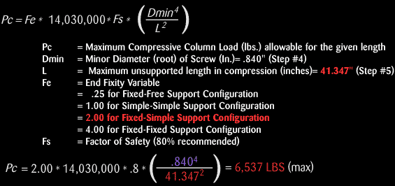
Step 9: Calculate Column Load Limit
This calculated column load is the maximum safe compression load allowable based on mounting arrangement, screw model and distance between bearings. In this example the calculated column loading should be greater than 500 lbs. (Step #2).
column load limit
Step 10: Calculate Drive Torque
Drive torque
Step 11: Calculate H.P. Required at Constant Velocity
hp required
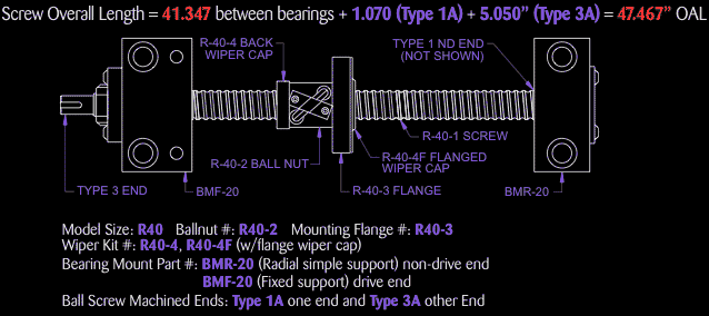
Step 12: Specifying Proper Ball Screw Assembly
proper ball screw assembly


Workshop | Products | Contact  
Copyright © NINGBO CIE INDUSTRY AND TRADE CO.,LTD. All Rights Reserved. Design By HiSupplier Online Inc.