| / We will do attentively.. | Collection / Supposes / E-mail / Site map |

|

| Industry News | |||||||
|
| Current Location: Home >> Products >> Power Transmission Parts >> Ball Leading Screw >> Steel rolled finish ball screw |
| Products |
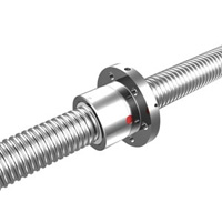
| Steel rolled finish ball screw |
 |
A ball screw is a mechanical device for translating rotational motion to linear motion. A threaded shaft provides a spiral raceway for ball bearings which act as a precision screw. As well as being able to apply or withstand high thrust loads they can do so with minimum internal friction. They are made to close tolerances and are therefore suitable for use in situations in which high precision is necessary. The ball assembly acts as the nut while the threaded shaft is the screw. |
Ball screws are used in aircraft and missiles to move control surfaces, especially for electric fly by wire. They are also used in machine tools, robots and precision assembly equipment. High precision ball screws are used in steppers for semiconductor manufacturing. Small ballscrews are often used to move the read heads of floppy discs and compact disc players. |
| The Following is rolled steel finish ball screw production technology information and list. |
| Product Images: |
 |
 |
 |
| Single and double nut ball screw | Ball Screw Series | Single and double nut ball screw |
 |
 |
 |
| Single and Double nut ball screw | Single and double nut ball screw | Single and double nut ball screw |
 |
||
| Single and double nut ball screw |
| Inner circulation ball bearing screw: |
 |
Model |
Metric diameter |
Journey |
Stationary hole |
Diameter of steel ball |
Installation and connection dimension of screw cap (mm) |
|||||||||||
D1 |
D4 |
D5 |
D6 |
L |
L1 |
L2 |
L7 |
L8 |
L9 |
L10 |
M |
|||||
CIE-0801R |
8 |
1 |
A |
0.8 |
14 |
21 |
3.4 |
27 |
|
|
16 |
4 |
18 |
10 |
2 |
|
CIE-0802R |
8 |
2 |
A |
1.2 |
14 |
21 |
3.4 |
27 |
|
|
16 |
4 |
18 |
10 |
2 |
|
CIE-1002R |
10 |
2 |
A |
1.2 |
18 |
27 |
4.5 |
35 |
|
|
28 |
5 |
22 |
10 |
2.5 |
|
CIE-1004R |
10 |
4 |
A |
2 |
26 |
36 |
4.5 |
46 |
|
|
34 |
10 |
28 |
10 |
5 |
|
CIE-1204R |
12 |
4 |
A |
2.5 |
24 |
32 |
3.5 |
40 |
|
|
28 |
6 |
25 |
10 |
3 |
|
CIE-1402R |
14 |
2 |
A |
1.2 |
21 |
31 |
5.5 |
40 |
|
|
23 |
6 |
26 |
10 |
3 |
|
CIE-1604R |
16 |
4 |
A |
2.381 |
28 |
38 |
5.5 |
48 |
72 |
10 |
38 |
10 |
40 |
10 |
5 |
M6 |
CIE-1605R |
16 |
5 |
A |
3.175 |
28 |
38 |
5.5 |
48 |
82 |
10 |
42 |
10 |
40 |
10 |
5 |
M6 |
CIE-1605L |
16 |
5 |
A |
3.175 |
28 |
38 |
5.5 |
48 |
100 |
\ |
50 |
10 |
40 |
10 |
5 |
M6 |
CIE-1610R |
16 |
10 |
A |
3.175 |
28 |
38 |
5.5 |
48 |
118 |
\ |
57 |
10 |
40 |
10 |
5 |
M6 |
CIE-1616L |
16 |
16 |
A |
2.778 |
32 |
42 |
4.5 |
53 |
\ |
\ |
38 |
10 |
34 |
10 |
5 |
M6 |
CIE-2004R |
20 |
4 |
A |
2.381 |
36 |
47 |
6.6 |
58 |
72 |
10 |
38 |
10 |
44 |
10 |
55 |
M6 |
CIE-2005R |
20 |
5 |
A |
3.175 |
36 |
47 |
6.6 |
58 |
82 |
10 |
42 |
10 |
44 |
10 |
5 |
M6 |
CIE-2005L |
20 |
5 |
A |
3.175 |
36 |
47 |
6.6 |
58 |
101 |
\ |
51 |
10 |
44 |
10 |
5 |
M6 |
CIE-2020R |
20 |
20 |
A |
3.175 |
39 |
50 |
5.5 |
62 |
\ |
\ |
47 |
10 |
41 |
10 |
5 |
M6 |
CIE-2505R |
25 |
5 |
A |
3.175 |
40 |
51 |
6.6 |
62 |
82 |
10 |
42 |
10 |
48 |
10 |
5 |
M6 |
CIE-2505L |
25 |
5 |
A |
3.175 |
40 |
51 |
6.6 |
62 |
101 |
\ |
51 |
10 |
48 |
10 |
5 |
M6 |
CIE-2510R |
25 |
10 |
A |
4.763 |
40 |
51 |
6.6 |
62 |
|
10 |
75 |
10.5 |
48 |
10 |
5 |
M6 |
CIE-2525R |
25 |
25 |
A |
3.969 |
47 |
60 |
6.6 |
74 |
\ |
\ |
57 |
12 |
49 |
10 |
6 |
M6 |
CIE-3205R |
32 |
5 |
A |
3.175 |
50 |
65 |
9 |
80 |
111 |
10 |
55 |
12 |
62 |
10 |
6 |
M6 |
CIE-3205L |
32 |
5 |
A |
3.175 |
50 |
65 |
9 |
80 |
102 |
\ |
52 |
12 |
62 |
10 |
6 |
M6 |
CIE-3210R |
32 |
10 |
A |
6.35 |
53 |
65 |
9 |
80 |
135 |
16 |
69 |
12 |
62 |
10 |
6 |
M8*1 |
CIE-3210L |
32 |
10 |
A |
6.35 |
50 |
65 |
9 |
80 |
162 |
\ |
90 |
12 |
62 |
10 |
6 |
M6 |
CIE-4005R |
40 |
5 |
B |
3.175 |
63 |
78 |
9 |
93 |
108 |
10 |
57 |
14 |
70 |
10 |
7 |
M6 |
CIE-4010R |
40 |
10 |
B |
6.35 |
63 |
78 |
9 |
93 |
137 |
16 |
71 |
14 |
70 |
10 |
7 |
M8*1 |
CIE-4010L |
40 |
10 |
B |
6.35 |
63 |
78 |
9 |
93 |
165 |
\ |
93 |
14 |
70 |
10 |
7 |
M8 |
CIE-5010R |
50 |
10 |
B |
6.35 |
75 |
93 |
11 |
110 |
171 |
\ |
93 |
16 |
85 |
10 |
8 |
M8 |
CIE-5020R |
50 |
20 |
B |
7.144 |
75 |
93 |
11 |
110 |
280 |
\ |
138 |
16 |
85 |
10 |
8 |
M8 |
CIE-5050R |
50 |
50 |
B |
7.938 |
90 |
112 |
14 |
135 |
|
\ |
107 |
20 |
92 |
10 |
10 |
M6 |
CIE6310R |
63 |
10 |
B |
6.35 |
90 |
108 |
11 |
125 |
182 |
\ |
98 |
18 |
95 |
10 |
9 |
M8 |
6310(Germany)R |
63 |
10 |
B |
6.35 |
90 |
108 |
11 |
125 |
182 |
\ |
98 |
18 |
95 |
10 |
9 |
M8 |
CIE-6320R |
63 |
20 |
B |
9.525 |
90 |
115 |
13.5 |
135 |
290 |
\ |
149 |
20 |
100 |
10 |
10 |
M8 |
8010R |
80 |
10 |
B |
6.35 |
105 |
125 |
13.5 |
145 |
182 |
\ |
98 |
20 |
110 |
10 |
10 |
M8 |
8010(P5 GERMANY)R |
80 |
10 |
B |
6.35 |
105 |
125 |
13.5 |
145 |
182 |
\ |
98 |
20 |
110 |
10 |
10 |
M8 |
8020R |
80 |
20 |
B |
9.525 |
125 |
145 |
13.5 |
165 |
295 |
\ |
154 |
25 |
130 |
10 |
12.5 |
M8 |
Model |
Ring number of ball bearing |
Dynamic rated load CaKN |
Static rated load CaKN |
Rigidity KN/μm |
|
F |
FM |
||||
CIE-0801R |
4 |
105.7 |
216 |
10.7 |
|
CIE-0802R |
3 |
142.2 |
238.8 |
8.2 |
|
CIE-1002R |
3 |
157.6 |
301.7 |
10.1 |
|
CIE-1004R |
3 |
301.8 |
453.9 |
10.4 |
|
CIE-1204R |
3 |
451 |
709.3 |
12.5 |
|
CIE-1402R |
4 |
235.2 |
569.8 |
18.6 |
|
CIE-1604R |
3 |
4.35 |
9.2 |
210 |
420 |
CIE-1605R |
3 |
7.65 |
13.2 |
230 |
460 |
CIE-1605L |
4 |
888.1 |
1525.4 |
22.1 |
43.1 |
CIE-1610R |
3 |
716.4 |
1232 |
16.6 |
32.3 |
CIE-1616L |
1.7*2 |
683.3 |
1298 |
18.6 |
\ |
CIE-2004R |
3 |
5.3 |
12 |
220 |
440 |
CIE-2005R |
3 |
8.6 |
17.1 |
240 |
480 |
CIE-2005L |
4 |
999.3 |
1994.7 |
27.3 |
53.2 |
CIE-2020R |
1.7*2 |
891.1 |
1795.2 |
23.2 |
\ |
CIE-2505R |
3 |
1119.4 |
2581.4 |
33.8 |
65.8 |
CIE-2505L |
4 |
1119.4 |
2581.4 |
33.8 |
65.8 |
CIE-2510R |
3 |
1903.3 |
3695.3 |
34.5 |
|
CIE-2525R |
1.7*2 |
1331.8 |
2805.4 |
29 |
\ |
CIE-3205R |
5 |
1264.1 |
3402.8 |
42.8 |
83.5 |
CIE-3205L |
4 |
1264.1 |
3402.8 |
42.8 |
83.5 |
CIE-3210R |
3 |
3092.6 |
6101.6 |
44.2 |
86.2 |
CIE-3210L |
4 |
3092.6 |
6101.6 |
44.2 |
86.2 |
CIE-4005R |
5 |
1407.1 |
4341.5 |
53.2 |
103.7 |
CIE-4010R |
3 |
3480 |
7979 |
54.6 |
106.4 |
CIE-4010L |
4 |
3480 |
7979 |
54.6 |
106.4 |
CIE-5010R |
4 |
3898 |
10325.7 |
67.5 |
131.6 |
CIE-5020R |
4 |
4621.1 |
11881.3 |
67.9 |
132.3 |
CIE-5050R |
1.7*2 |
4637.6 |
11221.9 |
58 |
\ |
CIE6310R |
4 |
4401.9 |
13611.2 |
84.3 |
164.5 |
6310(Germany)R |
4 |
4401.9 |
13611.2 |
84.3 |
164.5 |
CIE-6320R |
4 |
7401.1 |
19008.8 |
85.7 |
167.2 |
8010R |
4 |
4900 |
17366 |
106 |
207.4 |
8010(P5 GERMANY)R |
4 |
4900 |
17366 |
106 |
207.4 |
8020R |
4 |
8403.2 |
25345.1 |
108 |
210.1 |
| Feature of ball screw: |
1)Ball screw assembly is a high-precise mechanical drive part made up of screw, nut, ball bearing, sealing washer and other components, for there are ball bearing rolling between the screw and nut, the ball screw can receive high movement efficiency, compared with slide guide screw, the drive torque is under 1/3. So that it is easy to translate turning movement to straight-line movement, also, it is easy to translate straight-line movement to turning movement. It is a kind of further expansion and development of traditional slide guide screw. The profound significance of this development is the same as the transformation brought by rolling bearing to slide bearing. Due to its fine friction character, ball screw assembly is widely used in various industrial equipments, precise apparatus and precise numerically-controlled machine tool. Especially in recent years, work as executive unit of straight-line drive of numerically-controlled machine tool, it is broadly used in machine tool industry, and greatly promotes the numerically-controlled development of machine tool industry. All of these lie on several fine characters as follows: |
||||||||||||||||
| 2)It not only can feed slightly, but also can feed at high speed. Because of ball bearing’s rolling, ball screw has tiny starting torque, will not cause crawl or creepage phenomena, which are easy to come forth in slide movement, so that it can guarantee to realize precise micro feeding. On the other hand, with high efficiency, small friction and low heat, the ball screw assembly can carry out high-speed feeding at the same time. | ||||||||||||||||
3)Without clearance and with high rigidity. Adopt Gothic groove shape (refer to following picture), the axial clearance is regulated to infinitesimal and can not turn randomly. Besides, as the ball screw assembly can be added pressure in advance, the axial clearance can achieve zero or below zero even more after adding, thus high rigidity is received.  Gothic groove Gothic groove |
||||||||||||||||
4)Adopt inner circulation mode to work (refer to following picture)  This method is to make steel balls roll along the groove of inner circulator, get across the tooth peak of screw sidelong and return to origin. Generally speaking, a circle of steel ball implements a circulation. One end of the screw should be at least if using this circulation method, used in small screw diameter, adopt metal circulator. |
||||||||||||||||
5)Material and heat treatment
|
| Precision of ball screw assembly |
Feature of ball screw |
Precision of ball screw assembly |
Selection step of ball screw |
Safety use of ball screw assembly |
||||||||||||||||||||||||||||||||||||||||||||||||||||||||||||||||||||||||||||||||||||||||||||||||||||||||||||||||||||||||||||||||||||
| 1. Lead precision. Lead precision of ball screw of DAVID Mechanical and Electrical Making Co., Ltd. takes ISO 3408-4 as base, and according to using range and requirements, it is divided into orientation ball screw assembly (P) and transmission ball screw assembly (T), and the precision is divided into seven grades, they are 1,2,3,4,5,7 and 10, grade 1 is the highest. 2. Change volumes within random 300mm journey and 2 π radian journey are as follows:
1. Clearance at axial direction. Preloading grade of axial clearance of COMTOP precise ball screw is as follows:
1. Reference values of selected precision, clearance, preloading grade and screw cap
1. Clearance (P0) Rolled steel or Ground Grind ball screw (P0) max axial clearance Unit: mm
1. Reference value of preloading (P2) in common use
1. Precision of axis
|
|||||||||||||||||||||||||||||||||||||||||||||||||||||||||||||||||||||||||||||||||||||||||||||||||||||||||||||||||||||||||||||||||||||||
| page 1 | page 2 | |
| Ball Leading Screw | |||
|
| Other related category: | Auto Bearings, Industry Bearing, Auto Steering Gears |
| Relative Product : | Ball Leading Screw, Linear Motion Shaft, Linear Guide Rail And Block Assemblies, Precise Crossing Guide Rail |
| Workshop | Products | Contact |
| Copyright © NINGBO CIE INDUSTRY AND TRADE CO.,LTD. All Rights Reserved. Design By HiSupplier Online Inc. |
